CSIRAC - The First Australian Digital Computer - Emulation
Introduction
John Spencer wrote a number of emulators for CSIRAC around the turn of the century (2000).
These were written in Turbo Pascal for Windows 98. I have used the source code to resolve
some of the details of how various functions behave, but have completely re-written my
emulator in Java. The code has been tested, to some extent, on Windows and MacOSX, and
appears to work provided you have the Java 8 JRE, or later, installed. I have only been
able to test it more fully on Linux, as I only have Linux available.
Installation
The emulator can be downloaded here.
Installation depends on which Operating System you are running, but in general the
procedure is:
- Download the .zip file, using the above link.
- Unzip the archive which will create a folder called Jemu, containing the emulator,
my assembler, and various example files.
- To run the emulator you need to execute the command:
java -jar Jem.jar
in a command window.
I make use of a simple script to invoke the emulator, the File Jem.bat is a suggestion
for Windows. It can be improved by including the name of the folder, so that it can be
invoked from other folders, but I leave the details to you.
The Assembler, Casm.jar, is included and can be invoked in a similar manner, but expects
the name of the file to be assembler to be appended to the command line. I name my assembler
files with .casm as the qualfier, the assembler will, by default, replace the qualifier by
.cvt, which is the usual designation of a CSIRAC loadable file, to use for the output file,
plus a further file, replacing the qualifier by .lst gives an assembler listing, which I
find useful when debugging a program.
Emulator Overview
When invoked, the emulator displays four separate windows:
- The Displays window shows 6 CRT monitors,
- The Control Panel window shows the main control panel with switches and buttons,
- The Tape Reader window, which displays either of the paper tape readers, and
- The Printer/Punch window, which displays Printer output and punched tape output.
These windows can be re-arranged on screen to suit your preference. The Displays window is
fixed size, but the others can be re-sized in the normal way.
The Displays Window
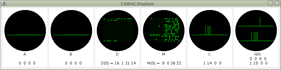
The six monitors displays the content of registers and store. From left to right we have:
- The A register, shown as an oscilloscope trace, with pulses for the bits. I have
provided very tiny pulses for zeros, and large pulses for ones. The least significant
bit is at the right end of the trace, which implies that the traces are drawn from right to left.
- The B register, in the same manner as A.
- The D registers. As there are 16 D registers, these are shown as a matrix of points,
which are expanded where there are one bits. D0 is at the top D15 at the bottom.
- The Store. Only 16 words are shown. The address of the top row is defined by the
six store address switches which appear at the left end of the second row of switches
on the control panel.
- The C register. This is in the same manner as the A and B registers.
- The H and S registers. This is not authentic. The S register was displayed on a
row of neon bulbs in the rack behind the control desk, but I preferred to display it
here, to avoid adding another window! The H register is displayed as the upper trace,
and the S register as the lower trace. The H register only has 10 bits.
I also display the current value in text form below each of the monitors. This is also
not authentic, but quite useful.
The Tape Reader Window
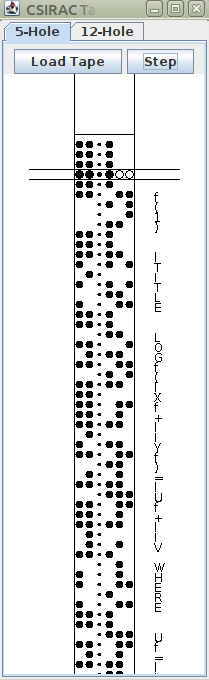
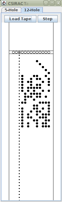
This window make use of a Java Tabbed Pane to display either of the tape readers. Click
on the tab at the top to select which one is visible. Use of the the Tape Reader 5/12 switch
on the control panel will also switch the readers. Note that the machine decides which one to
read based on the switch, not on which one is visible.
There are two buttons for each reader, Load Tape, and Step. Click on the Load Tape button to
pop up a file selection dialog, which should focus on the folder most recently used to load
a tape from, but you can navigate around the file store in the usual manner. Loading a tape
displays the tape with the first row between the two horizontal lines which represent the
read head.
The Step button will advance the reader by one row each time it is pressed. This is important
for the loading process as the loading procedure will start loading with the order under the
read head. It is normal to advance the tape to the first non-blank row before starting to load
a program. Some tapes have holes punched in a diagonal line to 'point' to the first real
row, these should also be skipped over.
For 5-hole tapes, I found it convenient to add a translation of the characters alongside the
tape. This is important when you start writing Interprogram tapes, as the error diagnostics
simply report an error and pause. On the original machine, the operator would mark the tape
with a pencil at this point so the error could be traced back to that point in the program.
The Printer/Punch Window
This window also uses a Tabbed Pane to display the Printer and the two tape punches,
although the punch displays are more along the lines of printers - showing the actual text
rather than the punched tape holes.
The three devices each have two buttons, Clear and Save, which are fairly self-explanatory.
The SAVE button pops up a dialog in the same manner as the reader Load Tape button, to specify
a file name for the displayed data to be saved.
The Control Panel
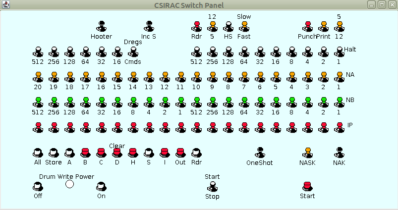
The main control panel was the central operating unit. Apart from loading and removing tapes
and printouts, and the main power switch, everything else was controlled from here.
The panel is arranged as seven rows of elements; from top to bottom:
- Various control switches,
- A row of six switches, a single switch, then a row of ten switches labelled Halt,
- A row of twenty yellow switches, labelled NA
- A row of twenty green switches, labelled NB
- A row of twenty red switches, labelled IP
- Eleven push-buttons, and three switches,
- Two buttons with a lamp between them, a switch and a push button.
Dealing with these from top to bottm, and left to right, we have:
- A switch labelled Hooter, which controls the sound. On the original machine this
was initially absent, control being effected by a volume control on the speaker unit. Later, the
volume control and the switch were moved to this panel. I have not implemented a volume control
for reasons which I will deal with when discussing sound output.
- A switch labelled ADD 1 and OFF. I am unsure as to the function of this
and it has no effect currently.
- Two switches which control the tape reader. The first is a power switch which has no effect.
The second, determines which reader will be read by the machine, up for 12-hole, down for 5-hole.
- A further switch which enables the trigger stop facility.
- A switch labelled Slow and Fast. This had various name changes, but I believe
it affected the speed of the machine. I have used it to slow down the emulation to an approximate
speed, especially the reader and printer, resembling the original. I make no claim as to how
accurate this is!
- After a gap two further power switches, controlling the punches, and the printer. Againm these have
no effect on the emulator.
- A final switch on the top row determines whether punched output goes to the 5-hole punch or
the 12-hole punch.
-
The second row starts with the previously mention row of 6 switches which determine the section
of the store to be displayed in the monitor. I have numbered these according to their effect
on the display, add up these numbers to get the address of the first store address displayed.
As the main store was implemented as 64 mercury delay lines, these switches are basically
selecting which delay line would be connected to the display.
- To the right of these, is a switch that, in the original machine, controlled whether the
D monitor showed the contents of the D registers, or the 16 previously executed instructions.
I have subverted this to control a trace facility. Putting the switch up turns on tracing,
which I will discauss later. Putting it down turns off tracing.
-
The remainder of the second row is a row of 10 switches, which specify an address. If the Halt
switch is on and the instruction at this address is executed, then the machine will halt.
-
The next three rows are all 20-bit switch registers. NA and NB can be accessed by program
using the NA and NB source function codes, while the IP register is ORed with data from the
tape reader whenread using the I source function code.
-
Row 6 begins with 11 push-buttons, which clear selected registers. The first one clears all
registers and main store, the second just the main store, the remainder individual specified
registers.
-
After the buttons, we have the OneShot switch. This causes the machine to halt after
executing a single instruction, thereby allowing the operator to step through a program
one instruction at a time.
-
NASK, or more properly NA&StoK, causes the machine to take the next order from
the NA switch register instead of the store. At the same time it adds in the value
in the S register. As the S register is normally incremented after each instruction,
successive instructions will operate with sequential addresses. I will explain this
more fully later.
-
NAK, or NAtoK, acts in a similar manner, but without adding in S.
-
The Bottom row starts with two buttons to control whether the drum store can be
written to, or not. The first button disables writing, while the second enables
it. Between them is a red lamp that comes on when writing is enabled. Later in
life, CSIRAC also had a 5-position switch which would enable writing to individual
tracks of the drum, or all four. I have only implement all or none.
-
The main Start/Stop switch is next. This can be used to halt the machine if it
seems to be misbehaving. Currently the emulator acts in a single-shot mode when
the switch is down, that is single instructions can be executed.
-
Finally, a push-button which triggers the machine into running. If the One Shot switch
is down, and Start/Stop is up, pressing the Start button commences, or resumes execution
of instructions. Otherwise, pressing the button will execute one instruction then halt.
This is probably unauthentic, but the documentation is unclear as to the exact relation
between these controls.
Bill Purvis, April, 2021