CSIRAC - The First Australian Digital Computer - Programming
In 1949 the arts and crafts of computer proramming was in its infancy. Initially the only
way to program a machine such as the CSIRAC was to write machine code, punch it onto
paper tape and see if it would work. A lot of the early work was done in this way, though
they very quickly realised that by creating a library of subroutines, you could make the
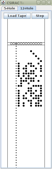
process much easier. In order to load a program into the machine it had to be punched in
a very strict format. Each instruction, or data word, being 20 bits, would have to be split
into two halves as the 12-hole tape could only represent half a word. By using ten bits
of a row for half a word, there were two extra bits which could be used to control the
loading process.
The loading process was controlled by a short sequence of code which was punched at the
start of every program tape. Although it was possible to set up the controls to copy tape
into store, it would only copy one row to each word. Fortunately, the data from tape was
copied into that part of the word which held the two function codes. By choosing suitable
orders, it was possible to devise a piece of code which could read in one or two rows from
tape, and pack them into a word, all without needing any order with an address part other
than zero. This piece of code, comprising 18 instructions, could then load a further extension
which would handle all the control neccesary to read in sections of code, resolving references
between them, and, if neccesary enter the code for execution. The first section of code was
named PRIMARY, and the extension CONTROL. When preparing a program tape, the
punch operator would simply copy this from a library tape onto the front of the new tape
and follow it with the user program.
Preparation of a program started by deciding which library routines would be needed, and
to order them so that any references between these could easily be resolved. This meant
that if routine A calls routine B, then B should be punched before A. Then the main program
would be written out in an unambiguous format reading for punching. I have not found a clear
description of the punching process, but I understand that it involved a special keyboard
which converted a sequence of keystrokes into 12-bit pattern which was punched onto the tape.

Image of main keys of the editing keyboard.
Above the keys was a row of lamps, two groups
of five, and a pair, representing the two base-32 numbers, and X and Y. Note that, in addition
to the number, there was also a mnemonic, or two if source and destination differed. The operator
would press two number keys, then X and/or Y. The appropriate lamps would light, and if
this matched the intention, a further key operated the punch mechanism, and the row was
punched onto tape. Some of the mnemonics differ from those in the
table, presumably conventions
changed over time, but the users would be aware of such differences.
In order to emulate the machine, and preserve the tapes for posterity, the existing library
and program tapes had to be transcribed into digital files. These files represent each row
of the tape by two base-32 numbers and two additional characters, which may be X or Y or
spaces. For convenience an additional space is added between the two numbers. So a line
which was written as:
10 27X
would be punched as:
        .Oo00.00.0.0.
	 Xf 27   10
where the '.' represent unpunched holes, and the 'o' is a feed hole, present on every row.
The loader behaves as follows:
A row is read in. If neither X nor Y is punched the number is added into a work register
for use subsequently. If X is punched, then the number is combined with work register to
make a 20-bit value, and is stored at the current load address. If, on the other hand,
the Y is punched, then special actions are taken, depending on the number.
Control functions were as follows:
| Code | Symbol | Function
|
|---|
| 0 0Y | m,nT | Set the load address to be m,n
|
| 0 n
|
| 0 1Y | nS | Store the load address as the n'th base address
|
| 0 n
|
| 0 2Y | nA | Add the n'th base address to the next command
|
| 0 4Y | R | Repeat the last control designation executed
|
| 0 6Y | D | Execute the next command instead of storing it.
|
Other codes were not used, or had special functions.
The Symbol column indicates shorthand notation used when writing programs.
The Punch operator would convert from this into the appropriate code sequence.
Typically each subroutine would be prefixed with the 1S symbol. Any relative addresses
needed in that routine would be prefixed with 1A so that the base address was added into
the address part of the instruction. In addition, each subsroutine would be assigned
an additional base address number, other than 1 and these were usually assigned in
sequence. Other routines could then use those numbers to modify references to those
routines.
Coding functions
As described in the architecture page, the CSIRAC
instruction word is made up of three parts: a source function, a destination function,
and a numeric value or address. The latter is not always used, only certain functions
require it. When an instruction is executed, the source function is first considered.
This normally produces a value which is referred to as the source. This value is then
passed to the second part of execution, where the destination function acts on the
source to perform some function. I will first look at the source functions, then
consider the destination functions in the following sections. I will use the memonioc form
of each function, but will follow it with the numeric vlue in parentheses. Where a numeric
or address value is needed, I will refere to this as n. Actual values would normally
be written in base-32 notation. Traditionally, the CSIRAC users wrote these as numbers in the
range 0 to 31, and when a number greater than 31 was needed, two numbers separated ny a comma
were written.
Source Functions
The simplest source function were simply the registers: A(4), B(11), C(14), S(23). Each of
gives the 20-bit number from that register. The bank of D(17) registers was similar, but as
there are 16 of these, the numeric value was used to specify which one. The least significant
four bits defines which of these is used. It is sometimes convenient to use n to
modify other functions at the same time, but the lowest four bits must match. Again, a 20-bit
number is produced.
In addition to the main registers, the store: M(0) can be used as a source. The 20-bit word
in location n is produced. In addition, there are four functions MA(27),MB(28),MC(29),
and MD(30) return a word from the drum store, the drum had four tracks, each holding 1024
words. MA to MD return words from track 1 to 4 respectively. The four tracks can be thought of
as together holding 4096 words, but you have to split that range into sections of length 1024
and use the appropriate function.
Other simple sources are the two switch registers: NA(2) and NB(3), and the tape readers provide
a further source: I(1). The value in this case depends on the switch selecting which of the
readers is to be used. The 5-hole reader returns bits P1 to P5, which the 12-hole reader
returns 10 bits in P1 to P10, and the X and Y holes set bits P19 and P20, respectively.
Each time the I function is invoked, the reader will advance to the next row. If the reader is
in the process of moving following a previous I operation, the machine will wait until
the move is complete and the data has settled.
The K(26) function returns bits P11 to P20 of the current instruction - this is the value
specified as n. Bit P1 to P10 are set to zero in this case.
Four other source function return explicit constant value: Z(20) return zero, PL(25) returns
1, PE(24) return 1024 (P11), and PS returns 524288 (P20).
The remaining functions extract bits or perform auxiliary actions.
Operations which involve the A register are: SA(5) which returns the sign bit of the A
register (P20). Bits P1 to P19 will be zero.
HA(6) returns half of the value in the A register, and TA(7) returns twice the value.
These are achieved by shifting right or left respectively by one place. In the case
of half of a negative number, the sign-bit is retained, so the value is valid. For
twice, it is assumed that the number does not overflow - that will happen if bit 20
if not equal to bit 19. Any arithmetic operations which involve this will be invalid.
LA(8) produces the lest significant bit of A, i.e. 1 or 0. CA(9) produces the value in
A, but then clears A, ready for some further operation.
Lastly, the function ZA(10) returns zero if A is zero, otherwise 1.
Operations on the B register are more obscure: R(12) tests the most significant bit of B. If that is
a one, it produces 1, otherwise 0. This is useful if you wish to round a double length
number, produced by multiplication to give a single length, rounded value.
RB(13) produces the value of B, but shift right by one place with the sign bit set to
be zero.
Operations on the C register: SC(15) produces the sign bit of the C register, similar to SA.
RC(16) return a positive half of C, that is it shifts it right one place. Unlike SA, it
does not propagate the sign bit.
Operations on the D registers, are almost identialc to those on C, except that the register
number is required as remarked for the D function: SD(18) produces the sign bit, and
RD(19) produces a positive half of the appropriate D register.
The H register is only 10 bits, so it can only produce ths ten bits. However, there are
two source function: HL(21) produces the ten bits in P1 to P10 position, while HU(22)
produces the bits in P11 to P20. The remaing bits in either case are set to zeros.
That concludes the source functions. We now move on to:
Destination Functions
As with the source functions, the simplest destination functions are those that simply
specify a register. A(4), B(11), C(14), S(23) and D(17) simply store the Source into the
corresponding register. Z(20) is what we now would call a no-op, discarding the Source
and performing no other action. Q(1) is a further no-op, action stated as 'no effect.'
PA(5) and SA(6) perform simple arithmetic with the Source and A, PA adds the Source to A
while SA subtracts it. CA(7) performas a logical AND between the two, whil DA(8) performs
a logical OR. NA(9) executes an exclusive OR function, so bits which differ between the
two inputs result in ones, while those that match give zeros. All thse operations leave
the resulting value in A.
PC(15), SC(16), PD(18), SD(19) perform the addition and subtraction operations as PA and SA,
but on the registers C and Dn, leaving the result in C or Dn.
The S register differs somewhat. PS(24) adds the Source to S. THis can be effective in
various ways. If the Source only has bits in P11 to P20, then this implements a relative
jump in the program. If the Source is negative, then the jump will be backwards, otherwise
it will be forwards. If, on the other hand the Source is less than 1024, that is only with
bits in P1 to P10, then the result simply adds that number into the low-order bits, provided
there is not an overflow into P11, in which case the next instruction address, which is
defined as bits P11 to P20 of S, will effectively skip one instruction. Combinations of these
two effects can be complex, but provided they are thought out can be useful!
The other instruction with S is CS(25). This examines the Source. If bits P1 to P11 of the
Source are non-zero, then P11 is added into the S register, effectively skipping the next
instruction. Further, if bits P15 to P20 are non-zero, again P11 will be added in. The net
effect will be either no skip, skip 1 or skip 2 instructions. This can implement a 3-way
test, but is more commonly used with the test source functions which only provide either
P20 or P1, in which case it is safe to assume eith no skip or a single skip.
The P(10) function transmits the source to a pulse generator which in turn drives the
loudspeaker. If used in a loop, a rather coarse tone is produced, the pitch being determined
by the frequency at which the pulse is sent. A simple loop including the P function and
a jump can generate a sound to alert the operator that the program has finished. Alternatively
a test of either the NA or NB switches can be used to exit the loop and procedd to some
other part of the program. The value passed to the pulse generator affects the volume in
some way - in general the larger the value the louder the sound.
M(0), MA(27), MB(28), MC(29), MD(30) simply store the source in either the memory or the
drum tracks as descibed for source functions. Note that writing to the drum is inhibited
unless the drum write enable button has been pressed.
OT(2) and OP(3) transmit the source to the printer (for OT) or the selected punch (for OP).
Again, the 5-hole punch operates using bits P1 to P5, while the 12-hole punch uses bits
P1 to P10 for ten bits, and P19 and P20 for X and Y. As for the readers, the printer and
punch ar elsower devices, and will hold up execution if needed. Note also that the character
codes for the printer and the 5-hole punch are different!
The H register, as stated above can only handle 10 bits. There are two destination functions
which are the inverse of the sourc e functions: HL(21) takes bits P1 to P10 of the Source,
while HU(22) takes bits P11 to P20.
The XB(12) function provides multiplication of two numbers. The Source is entered into the
B register, and then this is multiplied by the content of the C register and the resulting
39-bit result is stored: 20 most significant bits in A, and the remaining 19 bits in B, with
P1 of B being zero. Since there was no floating point arithmetic in these early machines,
much of the arithmetic work was done treating the numbers as scaled fractions. In that case,
if the Source and C were considered to be fractions, then the result in A would be the 20
most sigificant bits of the result. If, on the other hand, the two numbers were thought of
as integers, then the result would be an integer in B, multipled by 2, with a possible overflow into A.
Using the RB source would transmit the integer into another register and take care of the
fact that bit 1 of B was always zero.
The L(13) function had me greatly puzzled for weeks. The original Programming Manual describes
it as shifting the A and B registers left by x places where n=P20+2x
subject to x being in the range 0 to 7. Looking at the code in the W98 emulator
provided a puzzling effect if n was odd, the A and B registers get reversed.
After searching I eventually found the answer in an earlier Programming Manual, which used
a very odd notation for everything. In this, it explains that what actually happens is that
the A and B registers, togther with a one-bit register called Δ are linked together
and the sign bit of A is copied initially into Δ. The data is then rotated right for
20 bits, so that the content of A gets shifted into B, while B and Δ are shifted into A.
This effectively swaps the two registers. This then repeats the appropriate number of times
so that for every two cycles, the value in A,B is effectively shifted left one bit. According
to the earlier Programming Manual, the result of using an odd number for n is
'unlikely to be useful.'
Using the even numbers 0 to 12 gives left shifts of 1 to 7 bits, with any bits shifted
out of the most significant end of A being added in at the least significant end of B.
Symbolic Assembler
While the original coding method worked for the pioneers, it is somewhat tedious and error-prone.
I am a great believer in making use of modern facilities in conjunction with emulators, and
I have produced a symbolic assembler, called Casm, which makes it more convenient to prepare
progrmas on a PC, and produce a loadable file, without the need to be concerned about some
of the fine detail, such as actual address values. To simplify matters, and to make the format
more typical of modern assemblers, I have re-arranged the order of each instruction so that the
function codes are specified first, and any nueric or addressing values to follow. I allow
simple expressions, involving numeric values and symbolic labels with basic operators, '+', '-',
and '*', with a further operator for which I have used ':'. This last acts to shift the preceding
value left by 5 bits and then add in the following term. There is no operator precedence, but
the use of '(' and ')' to re-order evaluation can be used. Values are limited to the range
0 to 1023 (or -512 to +511) as the resulting 10-bit value must fit into the 10-bit field of
and instruction.
All instructions must begin with either a symbolic label, or some spaces (or tabs). Labels
can be a sequence of letters, digits and the underscore '_', beginning with a letter.
A label can be followed immediately by a colon, as I think it looks better, but this is optional.
Such labels are assigned the current address, but it is also possible to assign a different
value - for constants etc, by following a label by '=' and an address expression. In such
cases, the remainder of the line is ignored, so these should stand alone. A further option is
to substutute the character '*' for the label, in which case the current address is reset to the
value of the expression. Note that in either of these two cases, the expression must use
predefined values, as the value is derived during the first pass of the assembler.
Use of the destination function PS(24) is often used to effect a relative branch, and in this
case it is desirable to calculate the offset of a label, the use of 'label-*' will achieve
this, as in this context '*' can be interpreted as the address of the following order.
There is some scope for confusion here, as an expression such as '3**' means 3 times
the address of the next order, not an obviously useful expression!
I have designated the semicolon ';' to indicate comments. Anything following a semicolon,
up to the end of the line, will be ignored.
I have added two pseudo-functions: DC and DS. DC is used to define a 20-bit constant,
while DS defines a character string. As there are two character sets involved, I use
the single quote character "'" to indicate the code for the printer, while the double
quote character '"' indicates the code for the flexowriter.
It is assumed that a program will be totally self-contained, with subroutines included as
I have not made any allowance for linking to external addresses, other than via absolute
addresses.
Bill Purvis, April, 2021