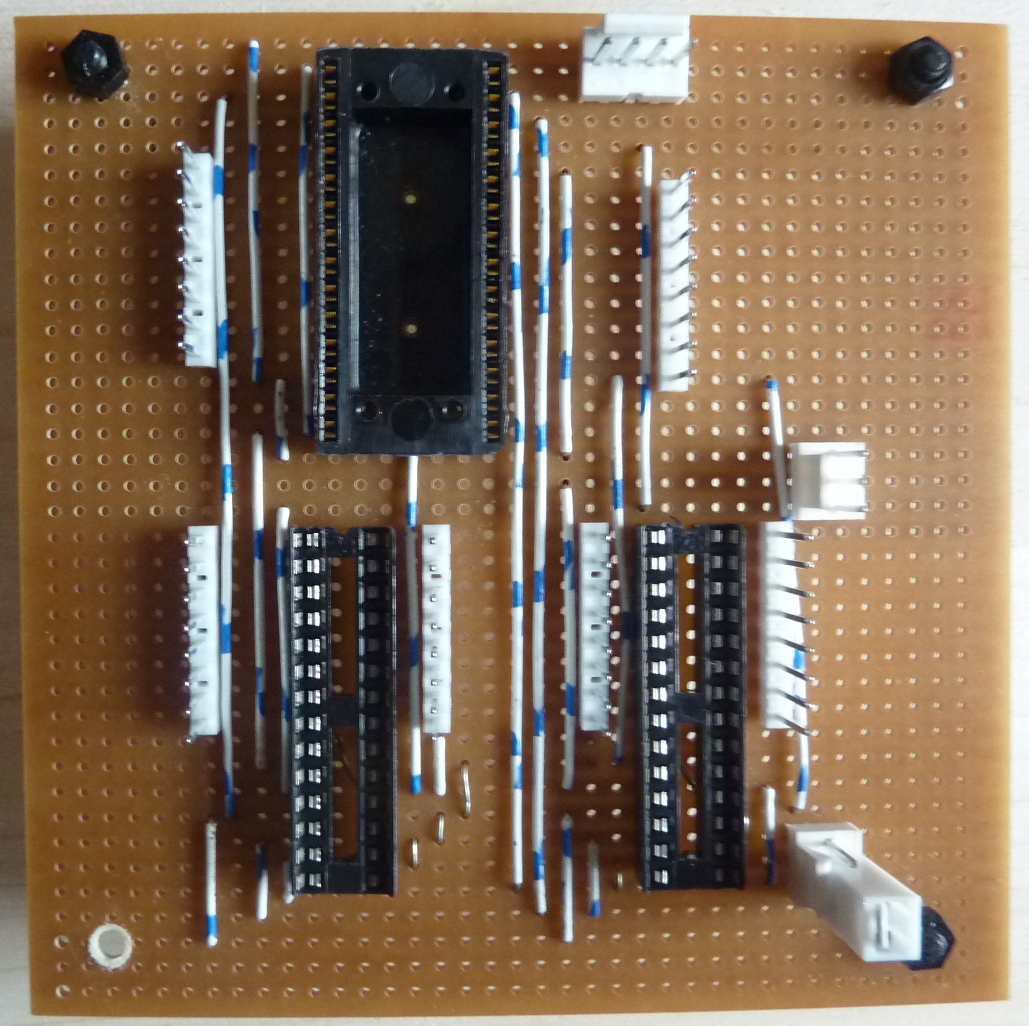
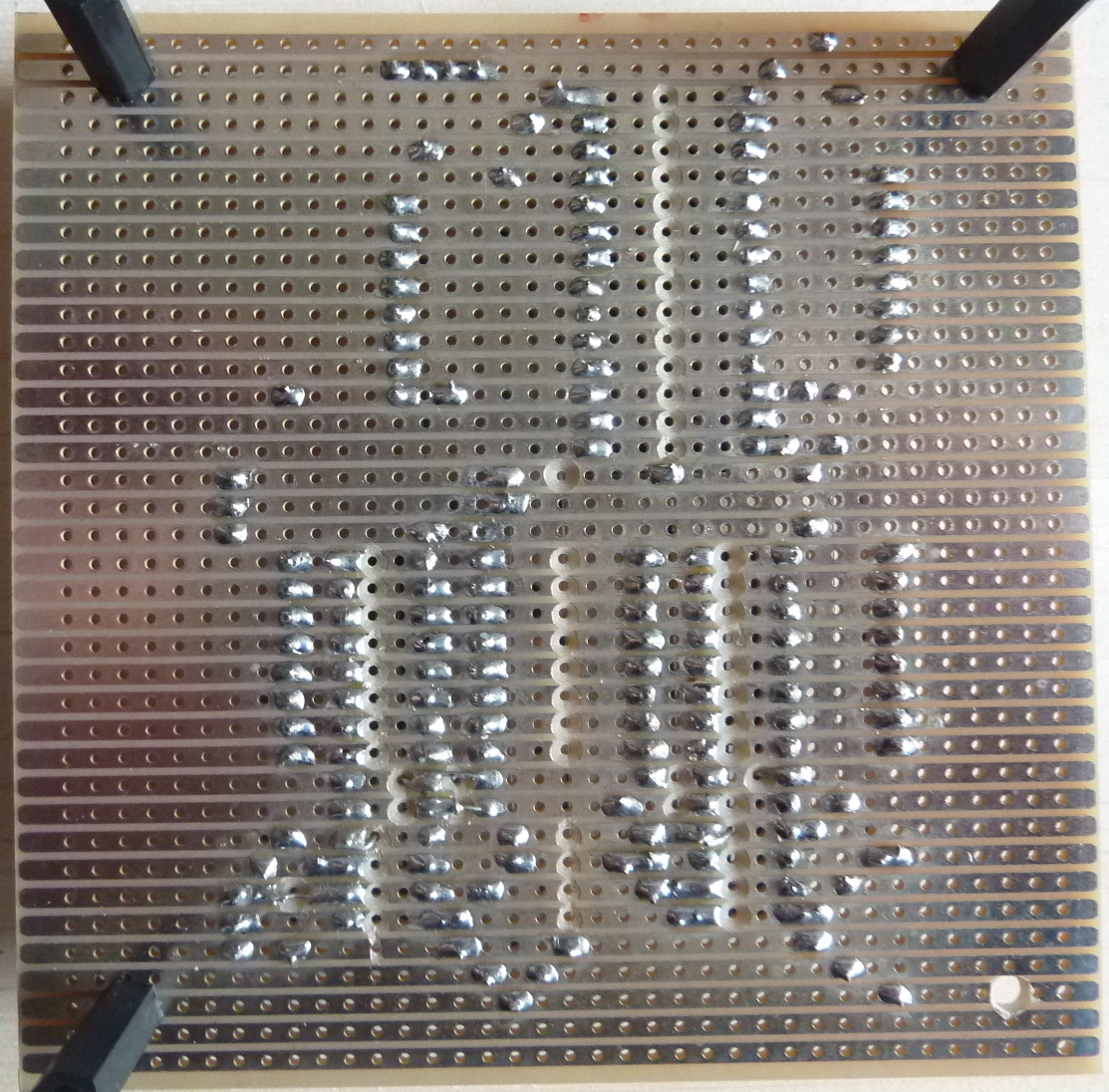
This is the prototype scanner board that I put together to check out before designing the PCB version.
At this time, there have been numerous changes to the original plans and this seems like a good time to bring things up to date.
Firstly, the original plan to convert the original keyboards to MIDI has fallen through. They keyboards were in a poor state and would require the ivory facings to be replaced - not a job that I fancied doing. Also the existing contact arrangements were somewhat battered and any modifications would probably not improve them. I came across an advert for a 5-octave MIDI keyboard at a very favourable price, and bought one to evaluate. I seemed to be a good quality keyboard, and the organist was happy with the idea, so a scond one was purchased. Midi keyboards come with a control panel at the left-hand end, which would not be required, and by cutting this, and the extra mouldings at the other end, we ended up with a keyboard which was almost an exact match, size-wise, for the originals. Encouraged by this we decided that it would be good to go for a three-manual instrument, and so a third was purchased, cut to size and there we have three manuals, with all the electronics included, only needing to be cabled into the PC.
Having decided on three manuals, the original proposed voicing was reviewed and extended and a search was made for suitable switches to act as stops. We had seen commercial instruments with rocker switches which illuminate when operated and searched for similar. They are hard to find! Eventually we found a Canadian firm that make components for DIY organs. They manufacture panels of rocker switches which look to be ideal, though they were quite pricey! Eventually, I ordered four panels of 16, giving a total of 64 switches. These were then allocated as stops and couplers to cover the proposed voicing. Thumb pistons and foot pistons were available in the UK, and these were also purchased and await fitting.
Although the need for keyboard scanners was obviated by the purchase of new keyboards, we still needed a couple, one for the stops and couplers, and another for the pedal board. A prototype board was assembled using matrix board and was made to work, but was felt to be rather large, and also might lack in reliability. A printed circuit board was designed and, thanks to a firm in China, produced at very reasonable cost. The first run revealed a slight design fault, so a corrected version was also produced. The faulty ones were not useless, and could be modified and used if ever a need for spares arose!
The pedal board was eventually rescued from it's temporary store and currently occupies a significant chunk of my workshop. The initial plan was to use the contact assembly which was housed in the base of the organ case, and add a scanner in the same manner as originally proposed for the keyboards, but after attempting to modify the cotact assembly, it was decided to discard it, and adopt a different technique.
This involved using read-switches, one for each pedal, which would be mounted on the end of the pedal frame, just above the ends of the pedal which project out to contact the original fingers that operated the original contacts. A tiny Neodimium magent was then inserted into a small recess drilled in the top of each pedal and test established that these would close the reed switch in the released position, and the switch would open when the pedal was depressed. The operation of reed switches, which are enclosed in a glass envelope, is very positive, fast, and with minimal bounce. When used by a scanner, it was found that bouncing was not a problem, as the time between successive scans seems to be more than any bounce, hence not noticed by the scanner.
Initially, the switches were mounted on small rectangles of matrix board with a slot in the middle to allow a certain amount of adjustment. These units were wired up to 4 cables, each with 10 cores, one of which was unused. This was convenient, as the connectors on the scanner board have 10 pins, 8 for signal inputs, ground and 5Volts. The 5Volt wire is unused in this application as the contacts simply connect to ground.
It was at this stage that the fault on the scanner board was encountered, and as production of new boards involves around 3 weeks delay (mostly for the post!) I had a rethink about the design. I then designed small PCB units to replace the matrix board elements, and ordered a batch of these. To reduce the cost, I designed a board with 8 of these units on it, and as the Chinese firm insist on producing 10 boards, I now have a surplus of these units! Cutting them up, and machining the slots, takes a little time, and was a bit of a chore, but all went well and I managed to clean up the required 32 units fairly quickly. These have a two-pin connector on them, so the soldered conncetions to the matric board will be replaced by connectors, which will allow the units to be swapped out and replaced if ever there is a problem with one. I'm hoping there won't be, but accidents do happen, and there could be a fault switch at some point.
In order to complete the organ we needed a computer. After consideration various components were ordered and acquired, and a PC was put together. This will live in the base of the case, but is currently on the bench in my workshop and is being used to test the various items.
To control the system, a small LCD display was acquired and connected to an Arduino processor. This will control the power distribution, and provide feedback to the organist. If power is connected to the organ, this will be powered directly and will therefore be on as long as there is power. One of the thumb pistons on the far right of the organ will be used to signal that the organ is required, and the processor will then operate a set of relays, firstly to switch on the PC, then, when the PC has had time to start up, it will signal to the processor that it is ready, and the power amplifiers can be enabled. On shutdown, which requires a longer press on the button, the audio amplifiers will first be switched off, then the PC will be signalled to initiate a shutdown, and finally the processor will revert into the off state to await being re-awakened.
Having read all the above, I now provide some photos of things as they are
at this time.
This is the prototype scanner board that I put together to check out before
designing the PCB version.
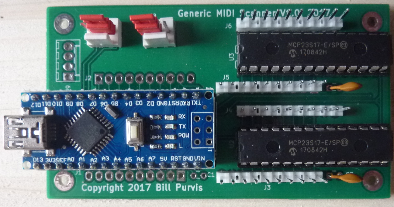
And this is the PCB version. It consists of an Arduino Nano processor and two
16-bit interface chips. The overall result has 48 i/o pins on 6 10-pin
connectors. Six of the i/o pins can be used to read analog signals, which
will be used to sense the position of the swell pedals.
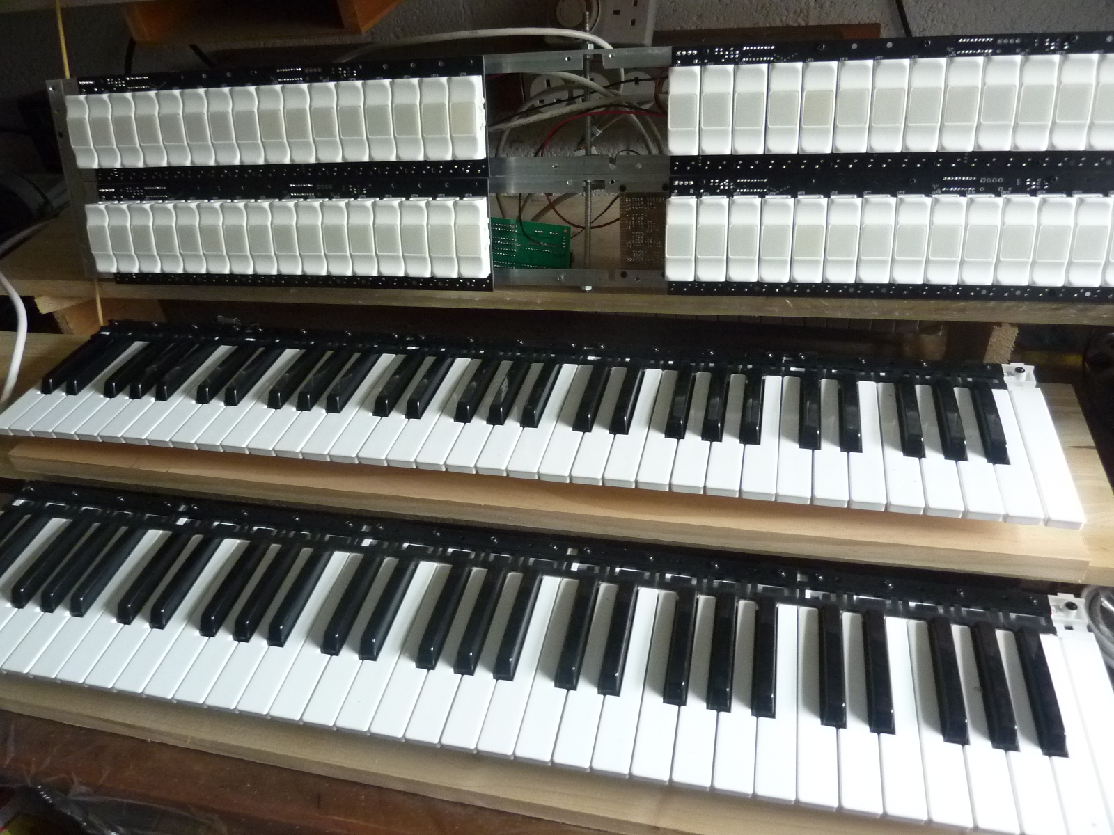
Here are two of the keyboards and a lash-up of the stops switches. |
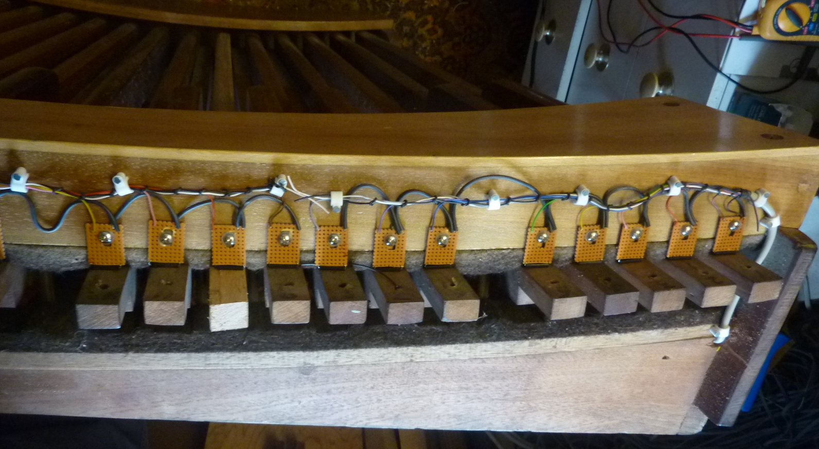
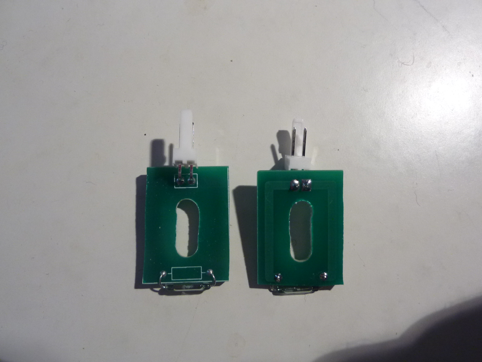
End view of the pedal board, or at least half of it. The reed-switch units here are the prototypes. To the right is a photo of two of the new PCD-based units awaiting being installed to replace the prototype units. You may notice that one of pedals (third from left here) is a distinctly lighter shade than the rest. When I was working on the pedals, one of them was badly warped and rubbed against the adjacent pedal. I therefore asked one of our friends if he had any suitable timber to make a replacement and he turned up a piece salvaged from the remains of the old building that was an almost perfect replacement. A slight adjustment of the shape at the end and there we are. It perhaps needs to be stained to make a better colour match, but at least it now operates without any binding or chance of it sticking! |

Bill Purvis
December 2017