Accumulator Shifting Unit 2
Accumulator
Main Adder
Computer Control I
Computer Control X
Computer Control II
Computer Control III
Computer Control IV
Computer Control V
Computer Control VI
Computer Control VII
Computer Control VIII
Computer Control IX
Coincidence Unit
Clock Generator
Complementer/Collater
Control Switches and Logic
Counter
Digit Pulse Generators
Engineers Control Panel
Frigs
Half Adder Type 1
Half Adder Type 2
Main Control Unit
Multiplicand Tank
Memory Units
Multiplier Tank
Order Coder
Order Decoder 1
Order Decoder 2
Order Flashing Unit
Order Tank
Printer
Sequence Control Tank
Initial Orders Loader
Timing Control Tank
Tank Address Decoder 0
Tank Address Decoder 1
Tank Address Distribution
Tank Address Flashing Units
Tank Address Decoding Final Stage
Tape Reader
Test Frigs
Transfer Unit
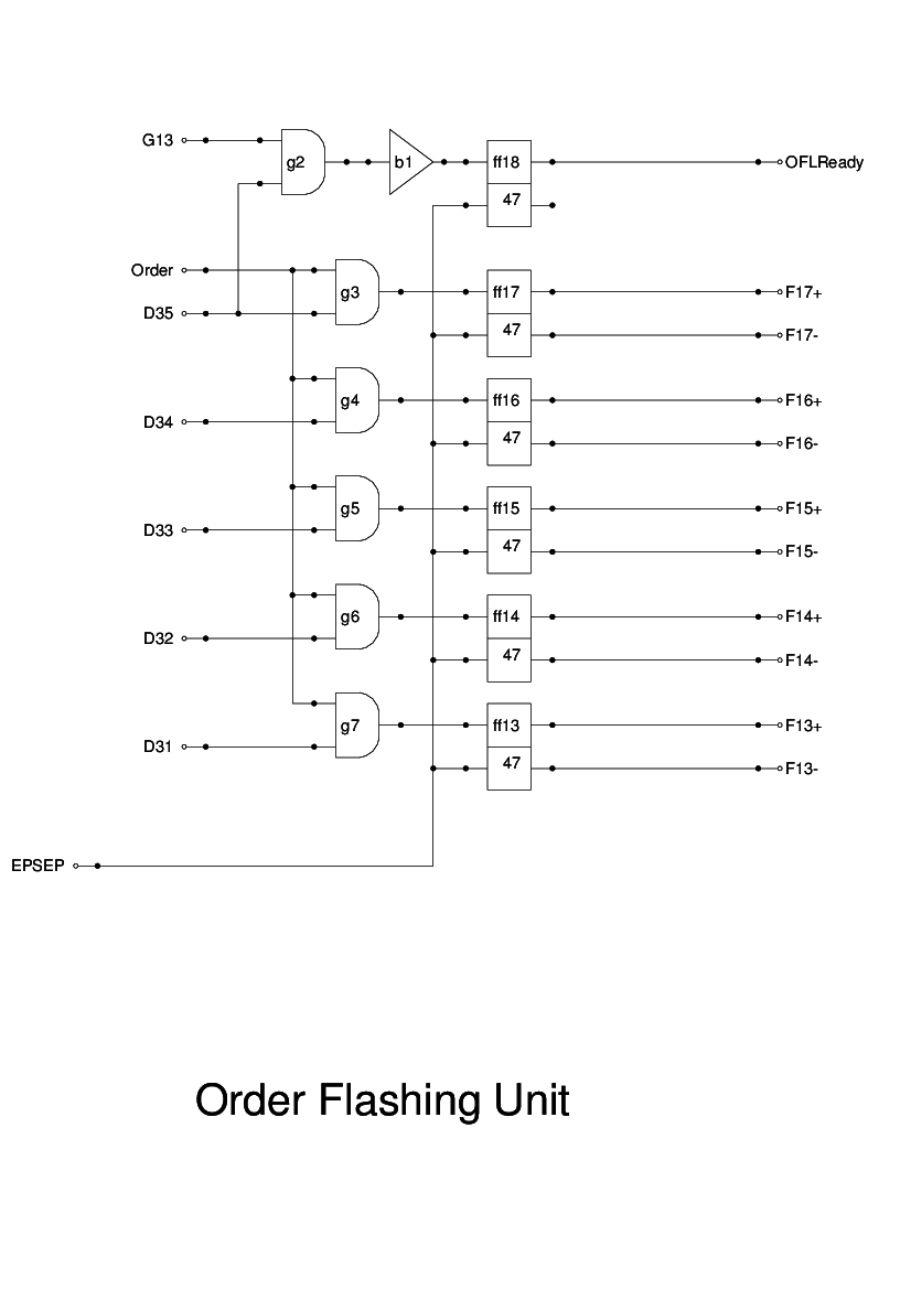
The Order Flashing Unit is simply 5 flipflops which are set by gating the Order pulse train with the specific digit pulses, D31 - D35.
The flipflops are reset by a pulse generated by a phantastron which is triggered by the negative edge of G12. I suspect that a phantastron is unnecessary, provided the flipflops can be reset by a negative spike. The pulse is also fed to the Tank Flashing Unit to reset the flipflops there at the same time.
One problem encountered was caused by the flipflops coming up in sequence: the Order Decoder would detect intermediate states and raise an inappropriate signal for a short interval. To prevent this, I have introduced gating on the negative output of ff17: F17-. This means that neither F17+ nor F17- are up until after the other flipflops have been set. This means that the Tank Decoder will produce no outputs until D35 sets ff18. The remaining flipflops will have been set to their required settings by this time and so no spurious decodes will be raised.
The text given in the Report is clear about how this is implemented, apart from the question of when the flipflops are reset. I have chosen to reset it using the trailing edge of G12 and EP. This seems to be satisfactory in simulations.
Since the design of flipflops given in one of the papers from the Archive has only a positive output, it will be necessary to provide inverters to generate the negative outputs.