Accumulator Shifting Unit 2
Accumulator
Main Adder
Computer Control I
Computer Control X
Computer Control II
Computer Control III
Computer Control IV
Computer Control V
Computer Control VI
Computer Control VII
Computer Control VIII
Computer Control IX
Coincidence Unit
Clock Generator
Complementer/Collater
Control Switches and Logic
Counter
Digit Pulse Generators
Engineers Control Panel
Frigs
Half Adder Type 1
Half Adder Type 2
Main Control Unit
Multiplicand Tank
Memory Units
Multiplier Tank
Order Coder
Order Decoder 1
Order Decoder 2
Order Flashing Unit
Order Tank
Printer
Sequence Control Tank
Initial Orders Loader
Timing Control Tank
Tank Address Decoder 0
Tank Address Decoder 1
Tank Address Distribution
Tank Address Flashing Units
Tank Address Decoding Final Stage
Tape Reader
Test Frigs
Transfer Unit
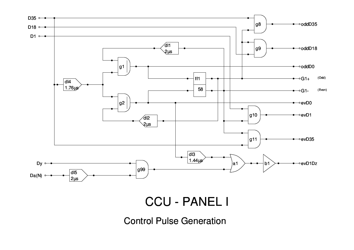
This is Panel 1 of the Computer Control Unit (CCU). The Computer, in Edsac terms, is what nowadays would be called the Arithmetic Unit.
This panel is a simple timing generator. Since the Accumulator is double length, we need to divide the minor cycles into odd and even cycles. All arithmetic operation begin on an even cycle, so we need various control pulses. This panel uses a flip-flop to toggle between the odd and even cycles, and the outputs from this are used to gate basic timing pulses to give odd and even versions.
The signals G1+ and G1- are fed to the Accumulator so that store instructions can access either of the accumulator tank and so do not need to wait for an even cycle. This would require more complex logic as the store gate can open at any half-cycle.
The circuit here is essentially as shown in the Report. The only change is the addition of the EvD1Dz signal, which is unspecified. I have found that using the logic here, the desired effect is achieved. It is used in the Complementer/Collater unit to reset the flipflop which is inserting trailing ones when a number has been negated.
One further change was to use a modified version of the D0 pulse. This is brought forward by several ticks to cope with the delays in the simulator. As a result, the outputs from this module are somewhat ahead of time for the same reason. I hope that these adjustments will be unnecessary in the replica logic.