Accumulator Shifting Unit 2
Accumulator
Main Adder
Computer Control I
Computer Control X
Computer Control II
Computer Control III
Computer Control IV
Computer Control V
Computer Control VI
Computer Control VII
Computer Control VIII
Computer Control IX
Coincidence Unit
Clock Generator
Complementer/Collater
Control Switches and Logic
Counter
Digit Pulse Generators
Engineers Control Panel
Frigs
Half Adder Type 1
Half Adder Type 2
Main Control Unit
Multiplicand Tank
Memory Units
Multiplier Tank
Order Coder
Order Decoder 1
Order Decoder 2
Order Flashing Unit
Order Tank
Printer
Sequence Control Tank
Initial Orders Loader
Timing Control Tank
Tank Address Decoder 0
Tank Address Decoder 1
Tank Address Distribution
Tank Address Flashing Units
Tank Address Decoding Final Stage
Tape Reader
Test Frigs
Transfer Unit
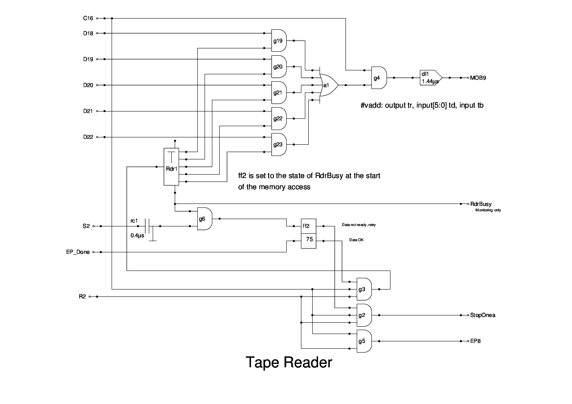
Only very sketchy textual details exist of the tape reader and its associated logic. The logic that I have produced is based on my interpretation of the text and may well differ from that used on the original. I consider that it is a reasonable guess as to how it might have been. If more details of the original can be found, then I will be happy to redesign the logic accordingly.
My design is based on a 'black box' device which emits a pulse train which defines the last character read from the tape. This is repeated every half-cycle. In addition there is a busy line which falls while the device acquires the next character. Inputs to the device are a trigger to signal that the current character has been read and stored, and so requests the device to commence reading the next character. A further input is just a reset line to indicate that the device should be reset to re-read the input file. This is impractical with a real tape reader and is simply used to perform any logic resetting needed.
The data output from the device is gated onto the MOB by the control signal C16 which is present only for an I instruction. When the coincidence gate has been opened to admit the data to memory, then the input R2 pulse would trigger an End Pulse at the next D0. However, the data may be that from the previous character, or could even have changed part-way through the transfer, and so we have to cater for this. This is done by monitoring the busy line from the device, and delaying it. If this delayed busy line is low, then the End Pulse is still sent, but at the same time the StopOnea- signal is dropped to suppress the increment to the SCT. This results in the instruction being re-scheduled and the whole process repeats until the delayed busy line indicates that the latest character has been delivered to memory.
The text of the report does suggest a somewhat different approach, but this has the merit of simplicity, and the approach suggested would require subtantial changes to the MCU.