Accumulator Shifting Unit 2
Accumulator
Main Adder
Computer Control I
Computer Control X
Computer Control II
Computer Control III
Computer Control IV
Computer Control V
Computer Control VI
Computer Control VII
Computer Control VIII
Computer Control IX
Coincidence Unit
Clock Generator
Complementer/Collater
Control Switches and Logic
Counter
Digit Pulse Generators
Engineers Control Panel
Frigs
Half Adder Type 1
Half Adder Type 2
Main Control Unit
Multiplicand Tank
Memory Units
Multiplier Tank
Order Coder
Order Decoder 1
Order Decoder 2
Order Flashing Unit
Order Tank
Printer
Sequence Control Tank
Initial Orders Loader
Timing Control Tank
Tank Address Decoder 0
Tank Address Decoder 1
Tank Address Distribution
Tank Address Flashing Units
Tank Address Decoding Final Stage
Tape Reader
Test Frigs
Transfer Unit
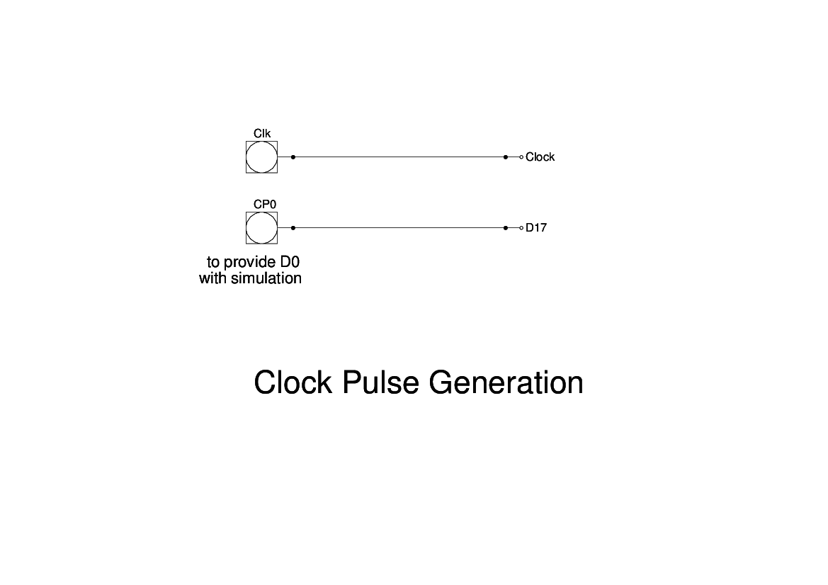
This is the Clock generation unit. This generates the basic timing pulses for use in the rest of the logic.
The elements at left are simulated pulse generators. The one nearest the top generates a continuous stream of pulses at 2.0 μsec intervals. Each pulse is 0.9 μsec wide.
The other two generate one pulse every minor cycle (36 clock pulses). In the original machine the clock oscillator was divided by 36 and the output was designated D17. The remaining pulses were generated by delaying the previous pulse by 1 or 2 pulse intervals. This caused me some problems in my simulation, and so I have inserted a pulse element to generate D0, so that my simulation starts with a D0 pulse. Simply ignore this and connect the delay 'dl0' to the output D0.
The clock does not appear on the original logic drawings, but the two main elements - the clock pulse generator and the delay elements appear in two circuit diagrams which were found in the Archives. The circuit for the delay elements specifies components for a 2 μsec delay, but it also says that there are twenty of these, in 5 panels of 4 stages per panel.
As not all the digit pulses are required, it was found that making some of the delays equal to two pulse intervals (4 μsec) that it was possible to produce all the required pulses with twenty stages. In order to do this we had to start from D17, which explains why this was chosen as the starting pulse.