Accumulator Shifting Unit 2
Accumulator
Main Adder
Computer Control I
Computer Control X
Computer Control II
Computer Control III
Computer Control IV
Computer Control V
Computer Control VI
Computer Control VII
Computer Control VIII
Computer Control IX
Coincidence Unit
Clock Generator
Complementer/Collater
Control Switches and Logic
Counter
Digit Pulse Generators
Engineers Control Panel
Frigs
Half Adder Type 1
Half Adder Type 2
Main Control Unit
Multiplicand Tank
Memory Units
Multiplier Tank
Order Coder
Order Decoder 1
Order Decoder 2
Order Flashing Unit
Order Tank
Printer
Sequence Control Tank
Initial Orders Loader
Timing Control Tank
Tank Address Decoder 0
Tank Address Decoder 1
Tank Address Distribution
Tank Address Flashing Units
Tank Address Decoding Final Stage
Tape Reader
Test Frigs
Transfer Unit
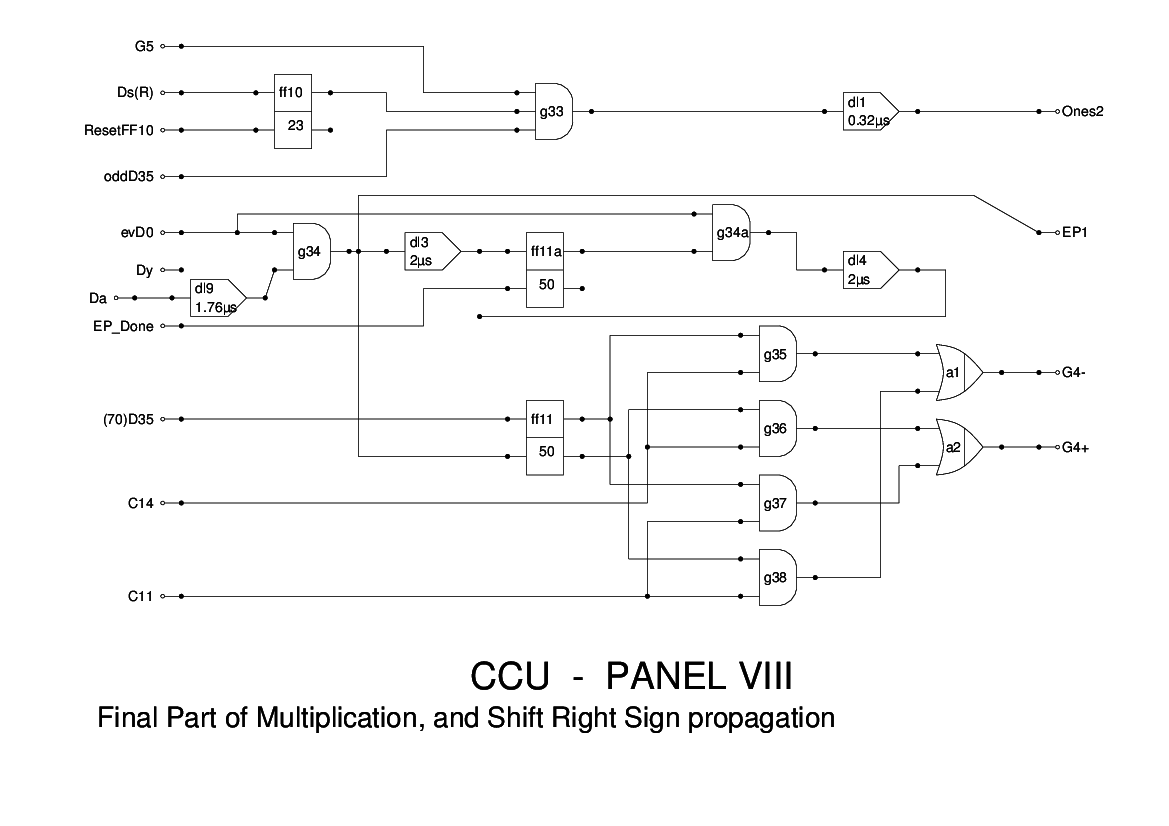
Panel 8 of the CCU serves for two functions. The logic at the top of this drawing relates to right shifts. If the value being shifted is negative, then this is indicated by Ds(R) which sets ff10. This in turn enables trailing ones to be added into the accumulator. For each double cycle of the accumulator a delayed evD0 is added until the flipflop is reset by ResetFF10.
The remainder of the logic is to do with terminating a multiplication instruction. The end of the instruction is indicated by the Dy pulse appearing at the same time as evD0. When this happens, an End Pulse (EP1) is generated to signal to the MCU that the operation is complete.
The remainder of the logic is concerned with handling the final addition or subtraction of a multiplication. If the sign bit of the Multiplier is set, that is, the Multiplier is negative, then this logic inverts the signals G4+ and G4- and so performs a subtraction instead of an addition or vice versa, depending on whether the instruction is V (multiply and add) or N (multiply and subtract).
The logic here is essentially that of Figure 15 of the report. The Y pulse of Figure 15 has been renamed as Dy for consistency with other units, in particular the Timing Control Tank, and adjustments to the timings were found to be neccesary in simulation.