Accumulator Shifting Unit 2
Accumulator
Main Adder
Computer Control I
Computer Control X
Computer Control II
Computer Control III
Computer Control IV
Computer Control V
Computer Control VI
Computer Control VII
Computer Control VIII
Computer Control IX
Coincidence Unit
Clock Generator
Complementer/Collater
Control Switches and Logic
Counter
Digit Pulse Generators
Engineers Control Panel
Frigs
Half Adder Type 1
Half Adder Type 2
Main Control Unit
Multiplicand Tank
Memory Units
Multiplier Tank
Order Coder
Order Decoder 1
Order Decoder 2
Order Flashing Unit
Order Tank
Printer
Sequence Control Tank
Initial Orders Loader
Timing Control Tank
Tank Address Decoder 0
Tank Address Decoder 1
Tank Address Distribution
Tank Address Flashing Units
Tank Address Decoding Final Stage
Tape Reader
Test Frigs
Transfer Unit
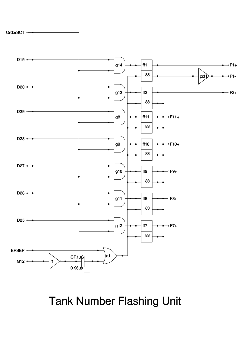
The Tank Number Flashing Unit is a group of flipflops, arranged to be set by clocking either the SCT (in Stage 1) or the Order Tank (in Stage 2) with the appropriate digiti pulses: D25 - D29.
The flipflops are reset at the same time as the Order Flashing Unit, and so the ResetFlash signal, produced there is used for this.
In addition to the tank number flipflops, there are two further bits in the instruction that need to be set: bit 1 which indicates the instruction length, and bit 2, which indicates if we are accessing an odd or even short word. Accordingly, there are two further flipflops which record these two bits from the instruction.
Once again, the decoding of the tank numbers requires both positive and negative outputs from the flipflops, so inverters will be needed here.
This unit is only given a textual description, but, as with the Order Flashing Unit, it is fairly clear apart from the resetting arrangement.