Accumulator Shifting Unit 2
Accumulator
Main Adder
Computer Control I
Computer Control X
Computer Control II
Computer Control III
Computer Control IV
Computer Control V
Computer Control VI
Computer Control VII
Computer Control VIII
Computer Control IX
Coincidence Unit
Clock Generator
Complementer/Collater
Control Switches and Logic
Counter
Digit Pulse Generators
Engineers Control Panel
Frigs
Half Adder Type 1
Half Adder Type 2
Main Control Unit
Multiplicand Tank
Memory Units
Multiplier Tank
Order Coder
Order Decoder 1
Order Decoder 2
Order Flashing Unit
Order Tank
Printer
Sequence Control Tank
Initial Orders Loader
Timing Control Tank
Tank Address Decoder 0
Tank Address Decoder 1
Tank Address Distribution
Tank Address Flashing Units
Tank Address Decoding Final Stage
Tape Reader
Test Frigs
Transfer Unit
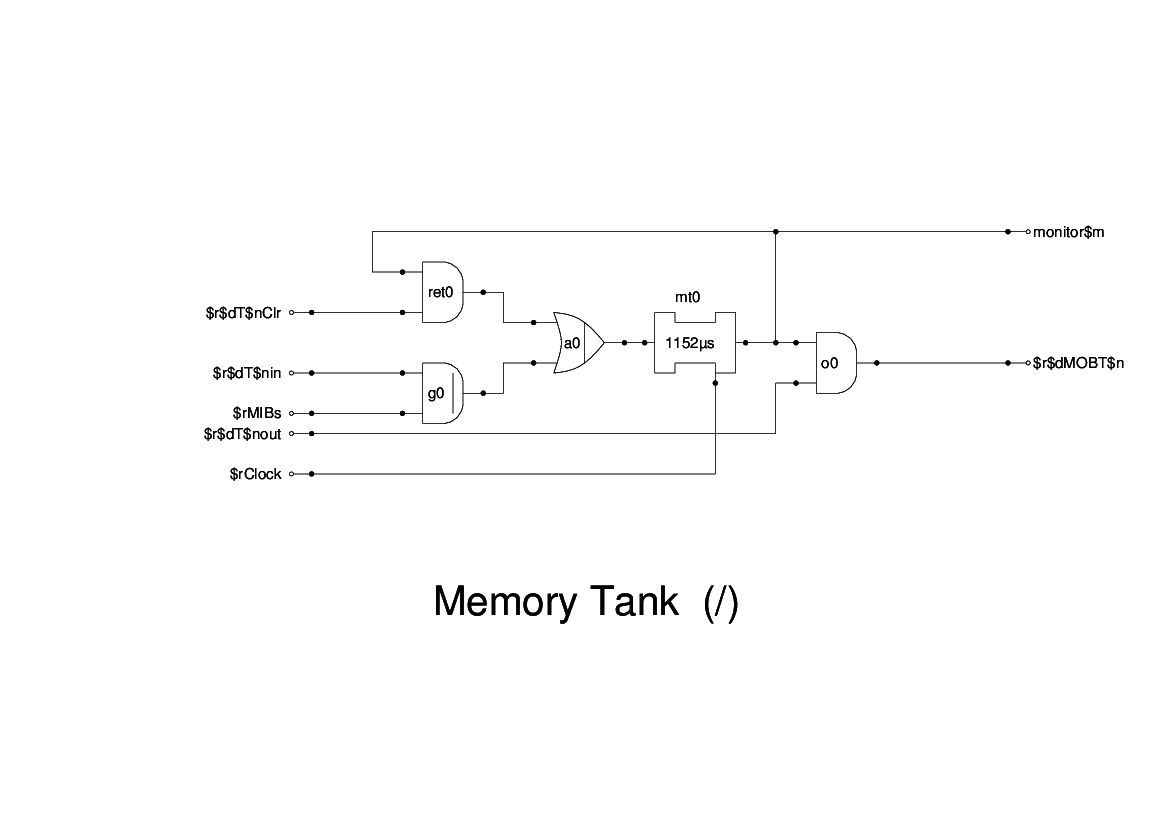
The Memory Tanks are long mercury delay lines. These were over 5 feet long and could hold 16 full words of data or 32 instructions.
For the purpose of validating the logic by simulation, I have only provided 4 of these, though the remainder could be added at a later stage if required.
The logic around each tank is identical and consists of input gating, output gating and recirculation gating. The following refers to Tank 0 but all the other tanks are essentailly the same.
The input gates are all connected to the MIB, while a control signal T0in is generated by the Tank Decoder unit to open that gate when:
- The particular Tank has been specified,
- The Coincidence Gate has been opened, and
- The instruction provides data to be stored in that tank.
I have shown an inverter from this signal inhibiting the recirculation path, but the original machine had a separate Clear input, which presumably came from an equivalent source elsewhere.
The Ouput gate is wire-ORed onto the MOB, though I have simulated this using three levels of OR gates, one here, and the other two in CCU Panel 6. The output is gated by the signal T0Out which is also provided by the Tank Decoder unit when:
- The particular Tank has been specified,
- The Coincidence Gate has been opened, and
- The instruction is one that requires data to be read from that tank.
Apart from the inverters r0, r1 etc. this is probably the closest we have to the original. A memory tank panel still exists at Cambridge, and we have reconstructed the circuit diagram from that. It also provides us with a template for constructing gates in other units.