Accumulator Shifting Unit 2
Accumulator
Main Adder
Computer Control I
Computer Control X
Computer Control II
Computer Control III
Computer Control IV
Computer Control V
Computer Control VI
Computer Control VII
Computer Control VIII
Computer Control IX
Coincidence Unit
Clock Generator
Complementer/Collater
Control Switches and Logic
Counter
Digit Pulse Generators
Engineers Control Panel
Frigs
Half Adder Type 1
Half Adder Type 2
Main Control Unit
Multiplicand Tank
Memory Units
Multiplier Tank
Order Coder
Order Decoder 1
Order Decoder 2
Order Flashing Unit
Order Tank
Printer
Sequence Control Tank
Initial Orders Loader
Timing Control Tank
Tank Address Decoder 0
Tank Address Decoder 1
Tank Address Distribution
Tank Address Flashing Units
Tank Address Decoding Final Stage
Tape Reader
Test Frigs
Transfer Unit
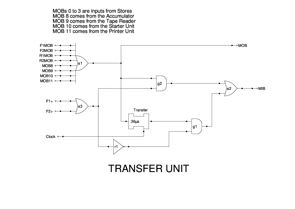
The Transfer Unit is provided to adjust short words coming from the memory via the MOB to make them appear as full words on the MIB. This only happens when a short word is read from an even address. The unit is, therefore, quite simple, and simply gates the MOB to the MIB if these conditions are not met.
If the conditions are met: bits 1 and 2 of the instruction are both zero, then the short delay line dl1 (18 bits) is introduced into the path and the number read appear is the correct timing for the arithmetic units to handle it.
The MOB has a variety of inputs of which the simulation shows 6 going into an OR gate. In reality, each of the inputs would be driven from its source via a diode, and the inputs here would simply be wired together into a cathode follower. This is nowadays described as a wired-OR connection.
Apart from the explicit OR gate a1 for the MOB the logic here is identical to that in Figure 8 of the Report.