Accumulator Shifting Unit 2
Accumulator
Main Adder
Computer Control I
Computer Control X
Computer Control II
Computer Control III
Computer Control IV
Computer Control V
Computer Control VI
Computer Control VII
Computer Control VIII
Computer Control IX
Coincidence Unit
Clock Generator
Complementer/Collater
Control Switches and Logic
Counter
Digit Pulse Generators
Engineers Control Panel
Frigs
Half Adder Type 1
Half Adder Type 2
Main Control Unit
Multiplicand Tank
Memory Units
Multiplier Tank
Order Coder
Order Decoder 1
Order Decoder 2
Order Flashing Unit
Order Tank
Printer
Sequence Control Tank
Initial Orders Loader
Timing Control Tank
Tank Address Decoder 0
Tank Address Decoder 1
Tank Address Distribution
Tank Address Flashing Units
Tank Address Decoding Final Stage
Tape Reader
Test Frigs
Transfer Unit
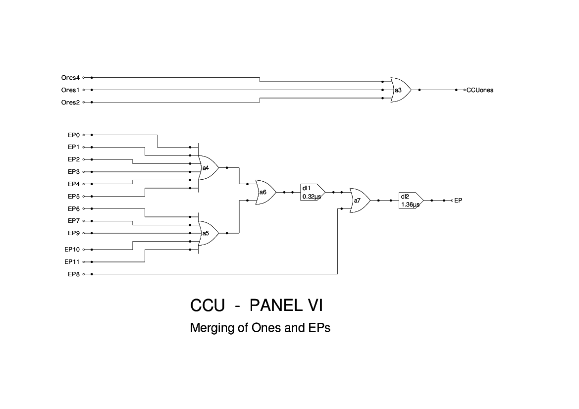
Part of Panel 6 has been shown in the drawing for Panel 5.
The remainder of panel 6 is simply two wired-OR gates. a3 merges the four signals used to insert ones into the Accumulator. These are shown in Figure 15 of the Report as internal connections, but they have been assigned individual names here. My view is that all inter-panel connections should have distinct names.
The other three gates should be treated as a single 11 input OR gate. This combines the various End Pulses prior to feeding the result to the MCU to terminate the current operation.
Figure 15 of the Report shows A4 as having 5 inputs, with a sixth being added subsequently. I have found it necessary to add a further 5 inputs for those sections that were not shown on the diagrams. I have also assigned names to all of these inputs for the above reasons.