Accumulator Shifting Unit 2
Accumulator
Main Adder
Computer Control I
Computer Control X
Computer Control II
Computer Control III
Computer Control IV
Computer Control V
Computer Control VI
Computer Control VII
Computer Control VIII
Computer Control IX
Coincidence Unit
Clock Generator
Complementer/Collater
Control Switches and Logic
Counter
Digit Pulse Generators
Engineers Control Panel
Frigs
Half Adder Type 1
Half Adder Type 2
Main Control Unit
Multiplicand Tank
Memory Units
Multiplier Tank
Order Coder
Order Decoder 1
Order Decoder 2
Order Flashing Unit
Order Tank
Printer
Sequence Control Tank
Initial Orders Loader
Timing Control Tank
Tank Address Decoder 0
Tank Address Decoder 1
Tank Address Distribution
Tank Address Flashing Units
Tank Address Decoding Final Stage
Tape Reader
Test Frigs
Transfer Unit
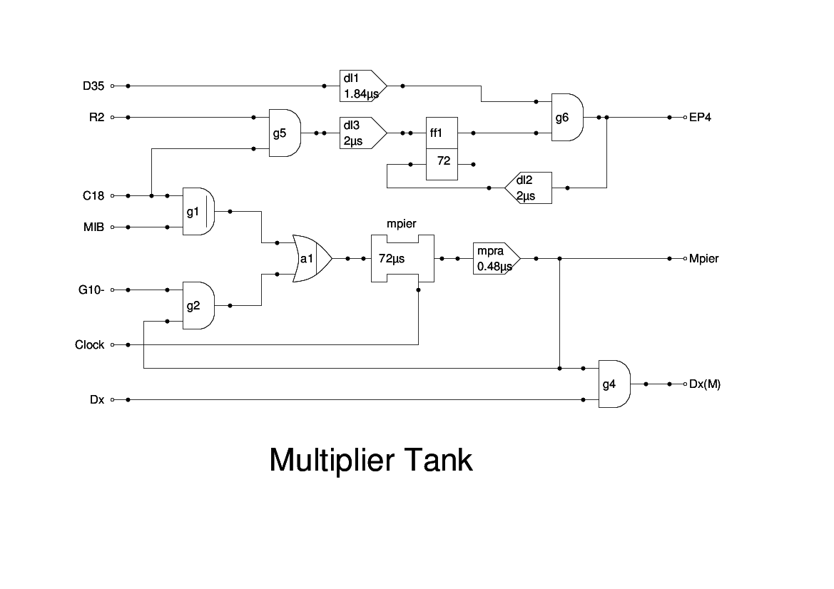
The Multiplier Tank, like the Multiplicand Tank, is a 36-bit delay line with recirculation.
Unlike the Multiplicand, there is no provision made for shifting the value. The only operations needed are loading, reading, clearing and testing bits.
The loading is carried out under the control of an H instruction (load multiplier). This is indicated by the signal C18. When this is present, the content of the MIB is written into the tank. It is assumed that the tank will already be clear, and the MIB will be clear until the required value is read from memory.
The completion of loading is indicated by receipt of an R2 signal from the MCU. This sets the flipflop ff1 which then gates the next D0 as an End Pulse (EP4). In simulation I have had to use D35 with a delay to get the End Pulse to time correctly. The End Pulse is then delayed by 1PI to reset the flipflop.
Reading the content of the tank, for the Collate instruction, is simply taking the output from the tank. This is gated in the Complementer/Collater Unit.
The Multiplier Tank is cleared by CCU Panel 9, which generates the G10- signal. This simply closes the recirculation gate and this is done at the start of Stage 2, before the Coincidence Gate can be opened.
Finally, the individual bits of the multiplier can be tested during multiplication by the Dx pulse which is generated by the Timing Control Tank logic. If the corresponding bit is a one, then Dx(M) is signalled, and this is tested in CCU Panel 7 and opens or closes the multiplicand output gate (G3+).
Once again, the Multiplier unit is only briefly described in the Report and there is no logic diagram. The above logic is therefore conjectural.