Accumulator Shifting Unit 2
Accumulator
Main Adder
Computer Control I
Computer Control X
Computer Control II
Computer Control III
Computer Control IV
Computer Control V
Computer Control VI
Computer Control VII
Computer Control VIII
Computer Control IX
Coincidence Unit
Clock Generator
Complementer/Collater
Control Switches and Logic
Counter
Digit Pulse Generators
Engineers Control Panel
Frigs
Half Adder Type 1
Half Adder Type 2
Main Control Unit
Multiplicand Tank
Memory Units
Multiplier Tank
Order Coder
Order Decoder 1
Order Decoder 2
Order Flashing Unit
Order Tank
Printer
Sequence Control Tank
Initial Orders Loader
Timing Control Tank
Tank Address Decoder 0
Tank Address Decoder 1
Tank Address Distribution
Tank Address Flashing Units
Tank Address Decoding Final Stage
Tape Reader
Test Frigs
Transfer Unit
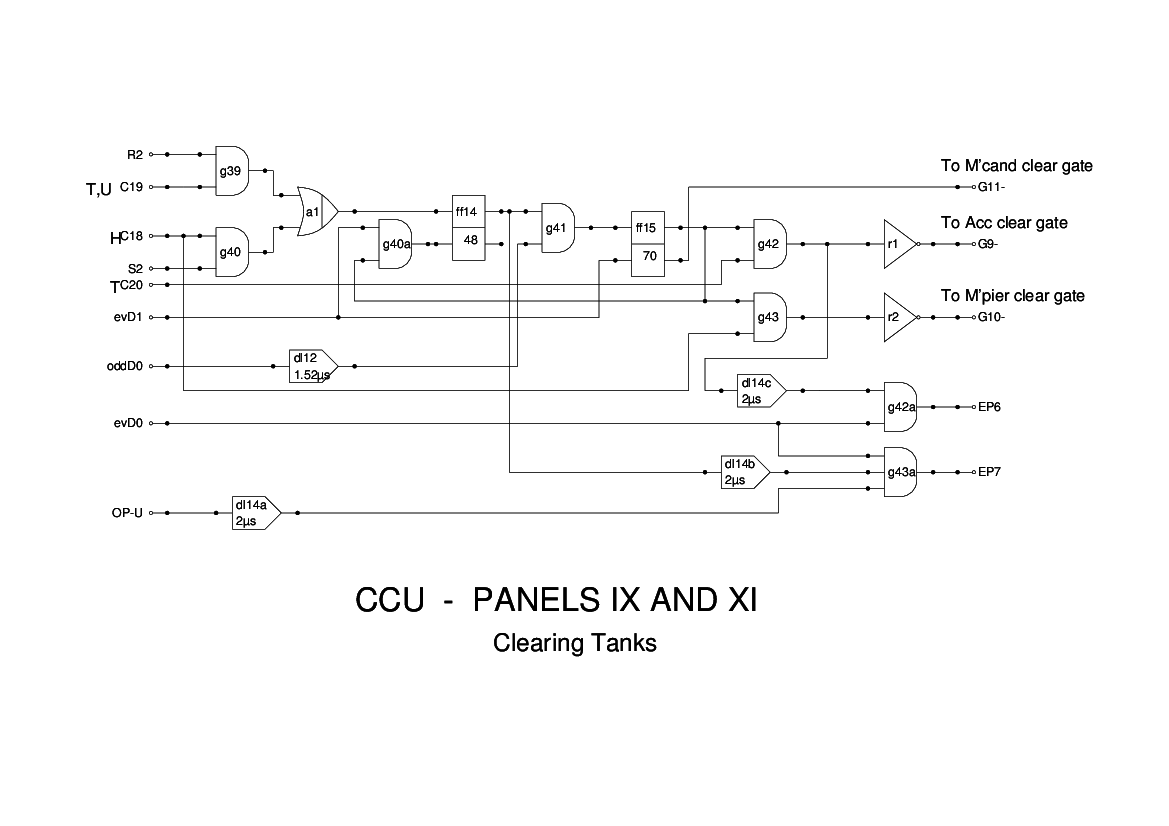
Panel 9 of the CCU generates signals to clear the arithmetic tanks when needed.
In the report figures, this is shown as Panels 9 and 11, but with no division indicated. I have taken some liberties with this module, and extended it to include generating End Pulses for the store/clear (U) and store (T) instructions.
The flipflop ff14 is set under the following circumstances:
- When a store (U) or store/clear (T) is being executed and has completed the transfer to memory.
- When a load multiplier (H) is about to be executed
g42 which gates it with C20 to produce G9- after being inverted. This closes the circulation gates on the accumulator and hence clears the accumulator.
g43 which gates it with C18 to produce G10- after being inverted. This clears the Multiplier Tank prior to loading the value from the memory.
At the same time, the negative output of the flipflop is used as G11- which clears the Multiplicand Tank.
The store/clear (T) instruction is terminated by an End Pulse in a phantastron, triggered by the falling edge of the output from g42, while the store (U) instruction is terminated by the next evD0 after ff14 has been set.
This module, as shown in Figure 15 of the Report, caused problems in simulation - there was no provision to generate end pulses, and there was logic in the Main Control Unit which was intended to avoid the need for these. During the devlopment of the replica logic it was found that this logic could not be made to work correctly, and it was decided that a cleaner way to achieve a working system was to add logic to this panel to generate End Pulses for the two store instruction. As the store+clear instruction needs additional time to clear out the accumulator, these need to be separate signals. I have used a phantastron to generate EP6 from the trailing edge of the output of g42 for the store+clear instruction. The basic store instruction (U) is terminated by EP7 which is derived from evD0.