Accumulator Shifting Unit 2
Accumulator
Main Adder
Computer Control I
Computer Control X
Computer Control II
Computer Control III
Computer Control IV
Computer Control V
Computer Control VI
Computer Control VII
Computer Control VIII
Computer Control IX
Coincidence Unit
Clock Generator
Complementer/Collater
Control Switches and Logic
Counter
Digit Pulse Generators
Engineers Control Panel
Frigs
Half Adder Type 1
Half Adder Type 2
Main Control Unit
Multiplicand Tank
Memory Units
Multiplier Tank
Order Coder
Order Decoder 1
Order Decoder 2
Order Flashing Unit
Order Tank
Printer
Sequence Control Tank
Initial Orders Loader
Timing Control Tank
Tank Address Decoder 0
Tank Address Decoder 1
Tank Address Distribution
Tank Address Flashing Units
Tank Address Decoding Final Stage
Tape Reader
Test Frigs
Transfer Unit
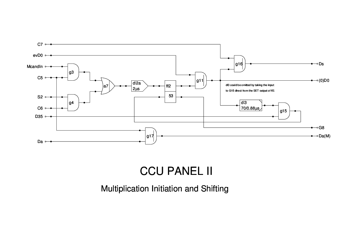
Panel 2 of the CCU is involved in initiation of multiplication and shifting instructions.
The logic is essentially that given in Figure 15 of the Report. The only change I have made is probably just a matter of notation. The original drawing shows the input to G3 as being from M'cand (Multiplicand), however, I found that the outpuit from the Multiplicand is firstly delayed by one minor cycle, and secondly is gated until needed by the remainder of the logic. I have substituted a new signal, McandIn (Multiplican Input) which is the pulse train being loaded into the Multiplicand tank. If the delayed output is used, then the signal G8 which prevents the addition/subtraction logic in CCU4 from taking control is too late to effect this.
One problem is that G8 is normally high. Our present understanding of the reversing element is that being AC coupled it can only be high for a limited length of time. In the absence of any multiplications then it would seem that this signal will drop and that will cause problems!
For multiplication C5 comes up, and provided the Multiplicand tank is non-zero, then the process is initiated by FF2 being set. This causes the next even D0 to be passed, as (0)D0, to the Timing Control Tank which controls the multiplication process. The signal G8 is used to inhibit the add/subtract logic in CCU4 from starting up.
For shift instructions, the Multiplicand is irrelevant and so FF2 gets set by the next S2 pulse. Again (0)D0 is passed to the TCT to control the shift operation.
The signal Ds is generated to test if the sign bit of the Accumulator is one when doing right shifts. The return pulse will enable propagation of the sign bit by inserting ones.
The Signals Da and Da(M) are associated with the multiplication and are used to test the sign of the Multiplier.