Accumulator Shifting Unit 2
Accumulator
Main Adder
Computer Control I
Computer Control X
Computer Control II
Computer Control III
Computer Control IV
Computer Control V
Computer Control VI
Computer Control VII
Computer Control VIII
Computer Control IX
Coincidence Unit
Clock Generator
Complementer/Collater
Control Switches and Logic
Counter
Digit Pulse Generators
Engineers Control Panel
Frigs
Half Adder Type 1
Half Adder Type 2
Main Control Unit
Multiplicand Tank
Memory Units
Multiplier Tank
Order Coder
Order Decoder 1
Order Decoder 2
Order Flashing Unit
Order Tank
Printer
Sequence Control Tank
Initial Orders Loader
Timing Control Tank
Tank Address Decoder 0
Tank Address Decoder 1
Tank Address Distribution
Tank Address Flashing Units
Tank Address Decoding Final Stage
Tape Reader
Test Frigs
Transfer Unit
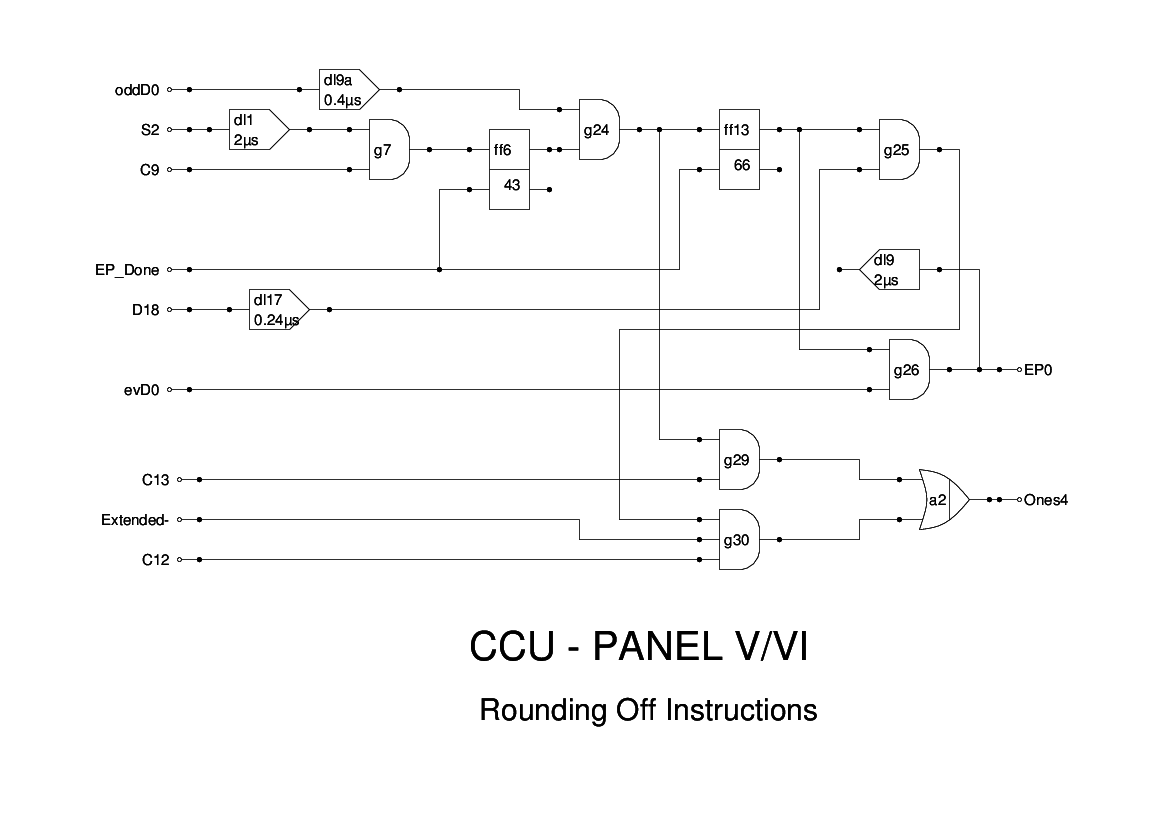
This drawing includes part of Panel 6 of the CCU as well as Panel 5.
Essentially, this is the logic for controlling the Rounding instructions.
As no memory access is involved, the action is triggered by the S2 pulse, gated with C9, but waits for oddD0 in order to add a one into the relevant position in order to round off the content of the Accumulator. Either oddD0 or oddD18 is added into the accumulator, then evD0 is used to generate an End Pulse (EP0). Note that both oddD0 and oddD18 are brought forward in time to align subsequent timings.
The logic is that of Figure 15 of the Report, apart from timing adjustments, and the moving of g29 and g30 from panel 6 to this drawing, and removal of g26 and Dw from this panel. Why the logic was laid out in this way originally is obscure.
One curiosity is the presence of two gates labelled g26 on the original drawings. The one concerned with the conditional jump has been removed as the logic for that has been altered.