Accumulator Shifting Unit 2
Accumulator
Main Adder
Computer Control I
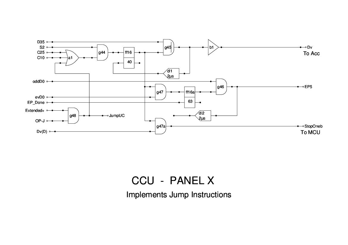
Computer Control X
Computer Control II
Computer Control III
Computer Control IV
Computer Control V
Computer Control VI
Computer Control VII
Computer Control VIII
Computer Control IX
Coincidence Unit
Clock Generator
Complementer/Collater
Control Switches and Logic
Counter
Digit Pulse Generators
Engineers Control Panel
Frigs
Half Adder Type 1
Half Adder Type 2
Main Control Unit
Multiplicand Tank
Memory Units
Multiplier Tank
Order Coder
Order Decoder 1
Order Decoder 2
Order Flashing Unit
Order Tank
Printer
Sequence Control Tank
Initial Orders Loader
Timing Control Tank
Tank Address Decoder 0
Tank Address Decoder 1
Tank Address Distribution
Tank Address Flashing Units
Tank Address Decoding Final Stage
Tape Reader
Test Frigs
Transfer Unit
Panel 10 of the CCU has been modified from the original as the two conditional jump instructions were originally designed as two separate bits of logic. I could not get the original logic to make sense, and so I modified that in Panel 10 to work, then decided it could just as easily handle both instructions by modifying the Accumulator logic to test for sign bit = 0 and sign bit = 1 depending on which instruction was being executed.
The S2 pulse from the MCU sets ff16 to start the instruction. This in turn issues the test pulse Dv to the Accumulator when clocked by oddD35. The next evD0 sets ff16a which then gates oddD0 to produce an End Pulse (EP5).
If the required condition is met, then Dv(D) will be triggered and this causes the inhibit signal StopOneb- to fall, which prevents the MCU from incrementing the newly loaded SCT. The MCU generates the signals (triggered by Dv(D)) which enable the SCT to be loaded from the Order Tank.